Hi,
I am very happy to see new Lens Distort TOP in experimental series, great work. I have recently done undistort in GLSL and therefore I have some ideas on how to possibly push this implementation even further to better suite various applications. Here are my two cents:
It would be great if Lens Distort TOP would have support also for newCameraMatrix. This way it would be possible to adjust scaling and positioning based on new camera matrix from getOptimalNewCameraMatrix().
I believe it would be best if Lens Distort TOP would always preserve native resolution of input texture. That means - if input has 2K resolution and Lens Distort TOP is set to 4K resolution, input is first scaled down to match its native resolution and then undistorted / redistorted. This way you can precisely specify ROI (that could be also generated by opencv getOptimalNewCameraMatrix()).
In my opinion the last part needed for complete control over undistort workflow is ability to specify custom scale and transform values. With these options it is possible to perform all sorts of undistort / redistort worklows.
To describe why would you want to have these types of controls, I might name a couple of workflows in following examples:
Classic VFX workflow
You undistort input camera, but you need to retain all original information (without loosing data around the corners). It is definitely not desirable to scale down undistorted image to fit original frame (since you would loose data). Therefore you just increase your resolution - so that stretched corners are still part of your undistorted image. You can then composite 3D render and redistort the image. This time you would lower your resolution to get back to original format.
Fixed format workflow
You undistort input camera, but it is not desirable to change the resolution. However you would like to keep as much data as possible, therefore you would use newCameraMatrix (from getOptimalNewCameraMatrix()) to properly scale input image.
Another fixed format workflow
You do steps described above but you realize getOptimalNewCameraMatrix() changes your aspect ratio when alpha=0. That might not be desirable. Therefore you might decide to use alpha=1. This would scale down your image (in case of barrel distortion) in order to completely fit it inside of original image format while keeping its aspect ratio fixed. This is not exactly what you wanted, but now you can use ROI to either crop it, or calculate our own scale and transform (based on ROI and original image format) that would essentially scale up your image back to perfectly fill original format.
I hope these features could be implemented as I wouldn’t have to maintain my GLSL undistort (I am using it for now as it has these features). I believe it isn’t too hard to implement, and it could open up a lot of possibilities for various use cases. Thank you very much for creating Lens Distort TOP.
Thanks for the feedback. It’s really useful to hear how you would use these OPs - particularly while they are still in the experimental phase.
I’m not familiar with the getOptimalNewCameraMatrix function in opencv, so I’ll need to do a little research there, but I had been wondering before about how to potentially implement a scaling feature.
With our Stype TOP that handles lens distortion for that system, we have a Padding value that sounds a little similar to what you’re describing. However, it only crops out the center of the image after the distortion is applied and does not change the resolution.
If I understand it, we’re potentially looking at a scale menu that lets you choose between options like optimal or custom scale/transform, and a toggle to either adjust the texture resolution according to the distortion or preserve the input resolution?
If I understand it, we’re potentially looking at a scale menu that lets you choose between options like optimal or custom scale/transform, and a toggle to either adjust the texture resolution according to the distortion or preserve the input resolution?
Yes, something like that, but I am not sure if such menu would allow for enough level of control as there are some scenarios where you might want to let user control these parameters. But on the other hand if you would cover also such scenarios it might be quite easy to operate.
In fact it might be theoretically quite cool if getOptimalNewCameraMatrix could be run directly inside of Lens Distort TOP (based on camera matrix, distortion coefficients and specified resolution). That could possibly work quite nicely - especially for variable camera matrices and distortions, but I haven’t tested this exact setup before.
However there would have to be some options on how to apply new camera matrix and ROI as user won’t have direct control over their adjustments. By adjustments I mean for example something like this
possibility not to move center of image with new camera matrix
possibility not to scale down image with new camera matrix - apply it just in case it needs to be scaled up (pincushion distortion)
possibility to keep aspect ratio untouched
possibility to read these calculated (and adjusted) values from info chop or as python attributes
Thanks for the further explanation and examples. I think I’ve got a better understanding of the workflow now.
My preference is to have options to both run getOptimalNewCameraMatrix internally as well as letting users enter their own new camera matrix and roi values. The resolution menu will have multiple options including taking the resolution from the optimal calculations, and using the custom resolution to increase the canvas size while maintaining the native resolution of the input.
I’ll post a test version when I’ve got something and you can let me know if it looks like it will handle your use cases.
Oh, that’s great! I am trying to figure out how to revive the augemented reality stuff I did in 2008 (touch077?). I was rendering onto a rectangle grid then bending the points around to compensate for the lens. This looks much more civilised.
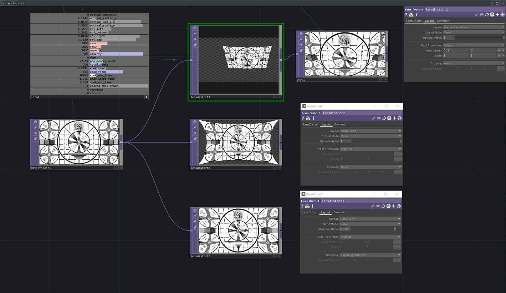
I’ve got the new LensDistort TOP features in now. We’re just doing some final testing and documentation, but they should be available in the next experimental release shortly. The screenshot below shows what the new Layout parameter page looks like as well as some basic examples of what it can do.
It was a little awkward trying to get all of the options to work together smoothly, but I think this should let you do everything. Under the hood it uses the opencv function getOptimalNewCamera matrix to calculate the best new scaling/offset values to fit the undistorted image, but you can also use your own custom values for transforming the image or cropping. The optimal values and the region of interest relative to the current transform are all available in the info chop.
There is also a Native Resolution layout mode that will maintain the resolution of the input image regardless of the overall image size.
Great, I am looking forward to playing with this new setup
By looking at the image I guess you have essentially converted data from getOptimalNewCameraMatrix to scale + transform values, right? That’s smart - much easier to look at.
I assume following equations for focal length would be therefore valid?
I guess something similar would also apply for the principal point, right? (I can see there is R for units, but I am not sure what it represents, I am just guessing here.)
Great to see optimal values in the info chop. With them it is possible for user to afterwards re-construct new camera intrinsics (in case the equations above are valid).
Yeah, I was trying to map the opencv features to something a little more general, but I’ll admit that, while all of the functionality is there, I’m not entirely satisfied with the interface.
Interestingly, it doesn’t actually work like you’re describing right now, but I may like your idea better.
In the current system, the new Post Transform parameters are actually direct translations of opencv’s new camera matrix. I did it this way so that you wouldn’t need to do the math you described and could use the values directly. However, it does mean the new scale/center parameters work inversely to the original center/focal length values which feels like it will be confusing.
I might take another look at it and consider applying the new transform as a modifier on the original C/F values rather than as separate values.
I’ve added new unit menus to replace the general ‘Camera Matrix Units’ menu from the current version. This is so that you can entering anything as either pixels or normalized/fraction values. You can also choose whether the center values are given in absolute coordinates (measured from the bottom-left), or relative to the center of the image.
The ‘R’ you noticed is for relative normalized units, so the center point is given as -0.5 to 0.5 relative to the center of the image. For opencv-based data, you’ll probably want to use the absolute-pixels units where the center is given as a pixel position measured from the bottom-left.
I see, this sounds good too - I guess it would be fine either way - both direct and modifier approach would work, the only difference might be in user experience as you mentioned. But I guess it would be just a matter of getting used to it.
Great, thank you very much, such unit menus will definitely come handy.
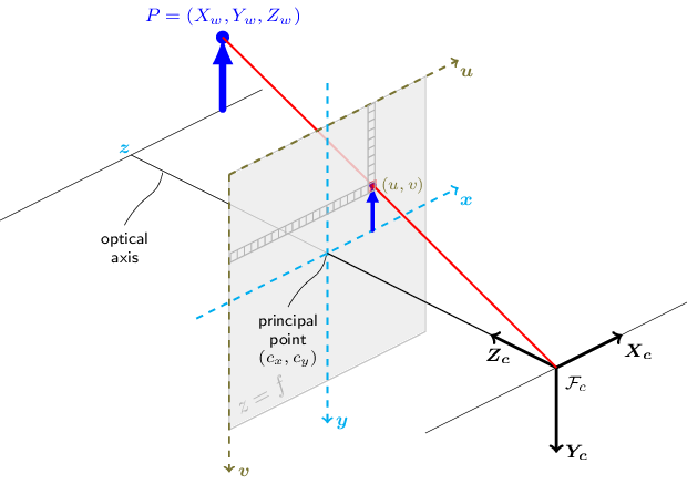
If I am not mistaken, opencv uses top-left origin (as could be seen on this image), right? However I guess you have flipped y axis for easy manipulation (which is great in my opinion).
Yes, it’s not an exact translation because OpenCV uses the top-left position as 0,0 where as TouchDesigner uses the bottom-left like OpenGL. We try to keep things consistent inside TouchDesigner, so internally I’m flipping the coordinates before calling the opencv functions.
@robmc I have just recently realized there is another, possibly much nicer lens distort workflow for real-time compositing and I thought I might share the concept here. This idea comes from UE4.27, where they implemented it this way:
Calculate overscan for render (rendering with overscan eliminates black borders when barrel distortion is applied)
Apply redistortion to render
This way it is possible to get render that could be composited with camera, while preserving full camera image (with no cropped pixels).
Classic VFX workflow first undistorts input from camera into larger format, performs compositing and then redistorts composite to match original distortion. This worklow skips the input undistortion and reformat which isn’t usually really necessary for real-time use-cases (as compositing isn’t as complex as in VFX world).
I guess the main problem is with calculating inverse distortion (redistortion) as it seems to be quite complex topic. However there are some interesting papers available on this topic. May I ask what approach does Lens Distort TOP currently use for distortion inverting?
Yeah, I think that’s the idea used in the Ncam/Stype workflows where both systems include a padded FOV value so that you can render with overscan and then distort the render to match the camera.
Regarding the inverse distortion: it’s definitely a big topic and we haven’t gotten into it very thoroughly. I don’t have the exact equations off hand, but we’re just using an approximation for the inverse of the formulas given on the docs page (https://docs.derivative.ca/index.php?title=Lens_Distort_TOP) I’m not sure they are accurate enough for production work, but can be useful for testing and prototyping.
Aha, I didn’t know Ncam/Stype use this distortion workflow - that is good to know, thanks! It surely sounds like a great workflow for real-time purposes.
Apart from inverse distortion problem, there is one more issue when going for this workflow. I have no idea what would be a proper approach for dealing with it, but I guess solving this issue would be essential if someone would like redistort overscanned render.
When distorting overscanned render, it would be needed to perform lens distortion in the final resolution (exactly the same way as it would be performed for that final resolution). It is kind of hard to explain so I am attaching sample file. overscan_distort_problem.toe (10.6 KB)
Thanks for the example … nice to see the new comments in use
If you set the focal lengths in lensdistort2 to 640 and 360 (the resolution before the overscan) and make sure the unit is in pixels, then the len distortion will be applied based on the original portion of the image and should match up with how the distortion would be applied to the non-overscanned image.
‘focal lengths’ is not the most intuitive name for those fields, but it seemed to be the most standard in opencv applications. In practice, it’s a scalar applied to the image before the distortion is calculated while the optical center works as an offset.
I think the naming is good the way it is - it was a good move to keep opencv naming convention as there are also many great docs / articles / images on this topic following the same naming conventions. I just forgot to look in there…